Rectifier circuit diagram Full wave rectifier bridge circuit diagram Rectifier half output voltage principle
Half Wave Bridge Rectifier Circuit Diagram
Rectifier bridge wave full circuit diagram diode voltage operation fig its shown below inverse peak disadvantages value when negative
[diagram] circuit diagram rectifier
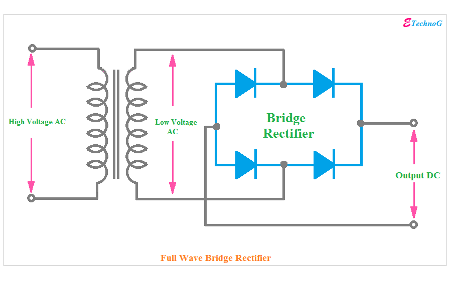
Full wave bridge rectifierFull wave bridge rectifier circuit diagram (4 diagrams) Half wave bridge rectifier circuit diagramHalf wave bridge rectifier circuit diagram.
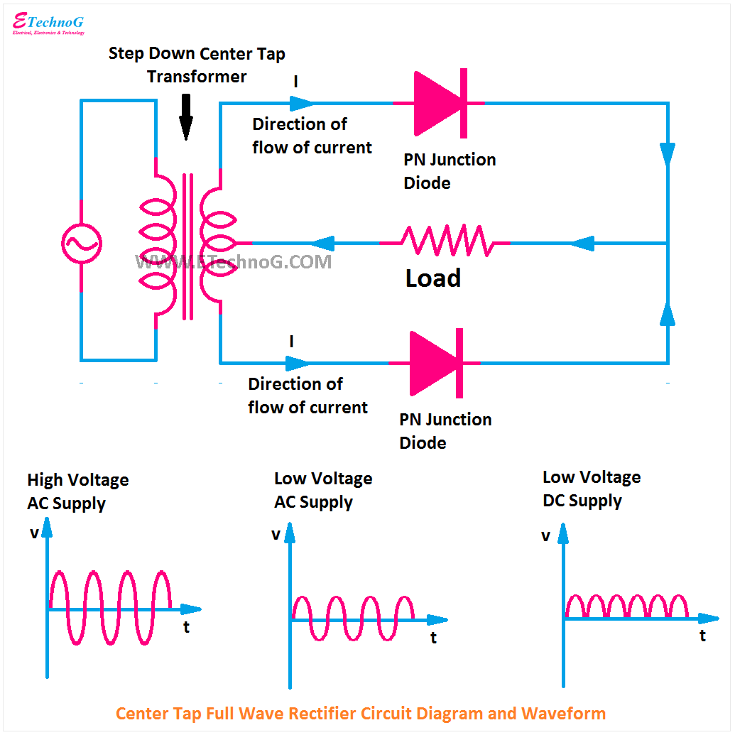
Draw the circuit diagram of full wave bridge rectifierHalf wave bridge rectifier circuit diagram Full wave bridge rectifier operationHalf wave full wave and bridge rectifier diagram.

Bridge rectifier circuit diagram and waveform
Rectifier operation diode diodes biased กระแส ไดโอด engineeringtutorialCircuit diagram of a bridge rectifier Full wave bridge rectifier schematicHalf wave bridge rectifier circuit diagram.
Half wave bridge rectifier circuit diagramSolved build the full wave bridge rectifier circuit shown in figure Half wave & full wave rectifier: working principle, circuit diagram.


![[DIAGRAM] Circuit Diagram Rectifier - MYDIAGRAM.ONLINE](https://i2.wp.com/circuitglobe.com/wp-content/uploads/2015/12/HALF-WAVE-AND-FULL-WAVE-RECTIFIER-FIG-1-compressor.jpg)


